Getting the $6 DC-DC converter working!
PLEASE NOTE: There are twelve pictures here, so please be patient while the page loads. :)
Note to HAMS: Here is how to REGULATE this thing!
This page contains the drawings & JPG photos illustrating the conversion of a small flourescent lamp unit into an effective DC-DC converter. Uses for these are, of course, not limited to Braille Display devices, they can be used in any portable aparatus requiring high DC voltage at relatively low current.
The lamp module used here easily provides approximately 200 volts DC at 10 milliamps, continuously. Note, however, that these units operate at approximately 47Khz AC, with a tremendous amount of radio frequency harmonics. If they are to be incorporated into any type of radio receiver, they MUST be thoroughly sheilded within a seperate metal box, and the input/output lines carefully RF bypassed to the chassis of the shield box.
Note that I have not used one of these modules in this capacity... I have ONLY used it to repair a Refreshable Braille Display device. These instructions are provided for that purpose. Any other use is at your own discretion and risk.
* WARNING * this unit will generate 200 volts or more! BE CAREFUL when working with it! Once the unit is modified, the capacitor can store that charge for some time, and the risk of a painful electric shock is very real, especially when the unit is operating! I know... I got bit by it, once! OUCH! <:(
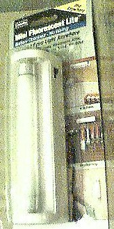
The brand name is "Amertac"™. Look in the upper left corner.
This unit is designed to use 4 AA batteries.
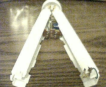
These are nice little lamps, so you may want to buy one, just to use it as-is!
At $6 each, it's a good deal... and you can keep the bulbs from the disassembled units as spares!
The
unopened unit |
 |
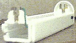
| Here are some pictures of the unmodified lamp driver circuit board: |
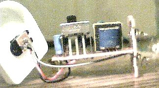
Here is a side view of the circuit
board. The power plug, battery
terminals and switch will be
removed. Keep for projects! | 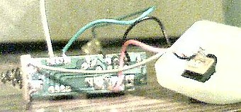
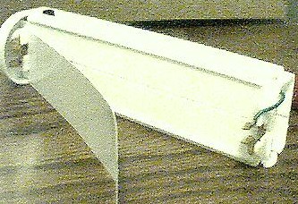
Bottom (foil side) view, showing
wires, etc. | 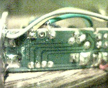
CLOSE-UP bottom view. |
| Here are some pictures of the MODIFIED board: |
This is the TOP view of the
Modified board. Note that the
switch and battery terminals
have been removed. | 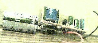
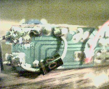
This is the side view. The
capacitor is soldered to the
pads which once held the
battery terminals in place. | 
This is the bottom view. The
foils leading to the pads where
the capacitor is were cut, to
isolate the HIGH VOLTAGE. |
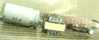
| Here are closeups of before and after: |
The Yellow & Green wires that
used to feed power to the bulb
were removed, and the output
of the small transformer is now
fed to the diode & capacitor
to create the 200v DC. |  |
A "solder bridge" is made between the terminal where the yellow wire was removed, and the (top) battery terminal pad right next to it. The pad where the green wire was removed has a foil going from it to another part of the board. THAT FOIL MUST BE CUT, as illustrated by the small red lines in the "BEFORE" image, above. The bottom battery pad has a thin foil running along the edge of the board, to another part of the circuit. THIS ALSO MUST BE CUT, as illustrated by the small red lines. The two battery terminal pads will then be used to solder the capacitor, and the bottom pad will also have the cathode end of the diode connected to it. The other end of the diode goes to the small pad where the green wire was removed.
It is important to cut those specific foils, so that the HIGH VOLTAGE portion of this circuit is ISOLATED from the low voltage portion! Failure to do this can either destroy this circuit, or the device which it will be powering! It can also dramatically increase the risk of a painful shock! Don't let the small size of this unit fool you! 200V DC is not something to treat casually!
It is important to note that the position of the diode & capacitor is significant. Because the output of this unit is not a 50% duty-cycle square wave, the DC voltage is stronger with the diode/cap configuration as shown, than it would be if reversed. BTW, the cathode end of the diode ALWAYS goes to the positive lead of the capacitor! This is critical! The capacitor can EXPLODE if connected backwards! <:-(
You will also notice that the RED WIRE is moved from the larger pad, where the switch was, to the smaller one to it's left. The red wire is where the 6V supply feeds the circuit. The black wire is the low voltage ground. The HIGH VOLTAGE is available at the Positive & Negative leads of the capacitor. I used a 22Ufd 250 volt cap. A small value such as this is more than sufficient, due to the high frequency of the oscillator. The diode AND capacitor should be rated at 300 volts or more, for a safety margin.
This page is now complete! There is one more page, with photos of the actual Braille Display device, and the steps to replace a defective module.
Please E-mail me with comments/suggestions.
NEXT PAGE
Return to HOME page
*** DISCLAIMERS ***
*ALL* Information presented here is done so without warranty or guarantee of any kind. Author assumes no responsibility for the use or inability to use this information. Author also assumes no responsibility for the ability or inability to complete the modifications, above.
Obviously, altering the flourescent lamp unit COMPLETELY VOIDS any and all manufacturer's warranties, and is done SOLELY AT THE MODIFIERS RISK. (No endorsement by the manufacturer was given, nor should be implied.)
This information is presented as educational information only. No guarantee is made as to its fitness for any purpose. All risk is assumed by the person who choses to use this information. While the author's experience indicates that this proceedure was effective in repairing a failed Braille Display device, any attempt to make these repairs IS AT YOUR OWN RISK. Extreme care must always be excercised, and it is strongly recommended that this proceedure ONLY BE PERFORMED BY QUALIFIED PERSONNEL. Again, this is at THEIR SOLE RISK.