
God Bless America!
N1NKM's Dual 12AU7 Radio |
|---|
Homebrew Receiver |
NOTE to modem users: this page has several 100K+ pictures, which may take a few moments to load. Please be patient.
| N1NKM's Dual 12AU7 Radio |
|---|
Homebrew Receiver |
NOTE to modem users: this page has several 100K+ pictures, which may take a few moments to load. Please be patient.
This page contains photos of my homebrew, 2-tube AM radio. It's yet another project that I did just for the sake of doing it. ;) I had the tubes, the chassis, etc. so HERE WE ARE!
NOTE: It was originally intended to use 12AT7's, but I had a couple of 12AU7's, so I used those, instead. :) They are pretty much interchangeable, and a 12AT7 would be fine in the RF socket. Since the 12AU7 is bigger, it's better suited for the audio stages.
I built it, start-to-finish, on Saturday, Oct 27'th, 2007! It was a rainy day. ;)
This project was inspired by a topic on the AMFONE.NET BBS. (The topic is now deleted. Sigh.) The schematic I used WAS posted in that topic. I modified it to match my parts pile, and also to add a MW notch, to eliminate the overpowering effect of two nearby stations. (One on 1300 and the other 1340 - kill 2 birds with one trap!) With just a few feet of wire, it picks up a number of MW stations, which is impressive! Performance on 75M is pretty good with the outdoor antenna!
Unfortunately, those two two AM stations, are only a mile away, so they get into everything. They tend to swamp the front-ends of many homebrew receivers when a larger antenna is connected. The MW notch filter in the RF preamp stage does a great job, here! It allows me to connect the outdoor antenna to pick up more distant MW stations! My best results, tho, are using my TUNED LOOP AM antenna. It gives me even better selectivity and sensitivity!
| Front view of radio |
|---|
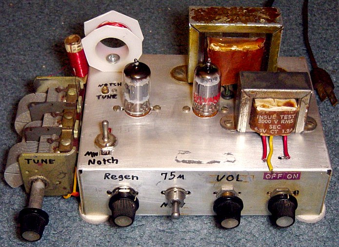 |
This chassis was originally a converter to bring 10, 15, or 20 meters down to the 75-80 band. It was only marginally functional, and unless one had a 75-80 only radio, not of much use. SO, I stripped it down to the power supply (which I rebuilt) replaced the aged tube sockets, and built this radio!
The tuning capacitor is huge, but it was the only 365pf unit I had. If I find a smaller one, I will use that. Yeah, it's UGH-ly, but for now, this works. ;)
On the left, is the Regeneration control. It works by varying the B+ to the plate of the regenerative RF stage. The optimum setting is a little below oscillation, where the audio level comes up and selectivity increases. Increasing beyond this point will cause the audio to become "muddy" as the Q is multiplied, and bandwidth reduced. Continuing to increase this will cause oscillation. This can be useful for SSB or CW reception, but not for listening to AM.
Above the REGEN control is the switch to put the MW notch into the ckt. (It is only needed on MW. it adversely affects the regeneration on 75M, so it must be switched-out.)
Between pots is the band switch. It simply selects between two seperate tank circuits. Since they are both Gnd referenced, only a simple DPDT switch is needed.
The next pot is the volume.
The smaller transformer in the front (a 6.3v filament tranny) connects to the speaker, which is in a seperate box. The larger transformer is the power supply. That sort of "octogonal" looking thing is the coil for Broadcast AM reception. It's just an old wire spool that I trimmed with tinsnips. Hey, I like BTN, ok? ;) The 75M coil is mounted vertically right next to it.
| Bottom view of radio |
|---|
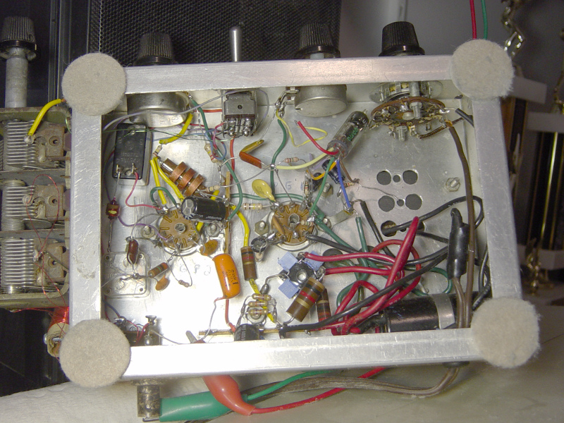 |
Here's the bottom side view. The RF preamp stage is the "top" half of the left tube, the regen stage is the "bottom" half. The big "orange drop" cap feeds the antenna input to the cathode of the grounded-grid RF preamp stage. The cathode RFC is clearly visible above the tube socket. A 15pf cap couples the preamp to the regen stage. The MW notch is connected at the plate of the preamp, thru a switch. The tuning cap for the notch filter was salvaged from a transistor radio. It is mounted just below/left of the RF tube.
The right-side tube is audio. The "top" 1/2 is the driver. The bottom 1/2 is the output. The added micro tube audio preamp stage is visible near the wafer style power switch.
The power supply occupies most of the "bottom" in this view. Approx 160V feeds the audio stages, 100v (regulated) feeds the RF stages. The small blue squares visible below the audio tube socket are .02 250v caps across each of the 4 legs of the bridge rectifier module. I am getting NO noticible hum in this receiver's audio! :)
Aside from the UGH-ly tuning cap and the funky-looking coil form, this is one of my neater-looking projects. :) It has decent sensitivity and selectivity for such a simple radio! Overall, I'm happy with it! Building it was a GREAT way to spend a rainy Saturday! :)
| Dual 12AU7 radio Schematic |
|---|
 |
Here's the schematic for this little beauty! It is somewhat similar to the original, as posted on the AMFONE.NET BBS (Which was long ago deleted.)
The major mods are the addition of a band switch, two fixed coils (rather than pluggable units) , the MW notch, and the extra audio gain stage. I also used zeners instead of an OB2 to regulate the B+ to the RF stages. The grounded-grid RF preamp really does help a LOT to reduce antenna effects on the tuning and regen. It also very effectively blocks 99% of re-radiation, which is always a concern with regen receivers. I later added a 6111 micro tube for additional audio gain. It made a HUGE improvement in volume, making this radio much more enjoyable to listen to.
*** DISCLAIMERS ***
(Keep the lawyers happy.)
*ALL* Information presented here is done so without warranty or guarantee of any kind. Author assumes no responsibility for the use or inability to use this information. Author also assumes no responsibility for the ability or inability to complete the project, above. This project uses potentially harmful voltage! (160VDC) If you are not sure of what you're doing, ask an experienced friend to help. ALWAYS "pull the plug" and ground the caps to make sure there is no high voltage when working with this unit.
This information is presented as educational information only. No guarantee is made as to its fitness for any purpose. All risk is assumed by the person who chooses to use this information.