
God Bless America!
N1NKM's 1-tube BTN AM Radio!
N1NKM's HAM page 7 |
|---|
1-tube AM radio |
NOTE to modem users: this page has several 50K+ pictures, which may take a few moments to load. Please be patient.
| N1NKM's HAM page 7 |
|---|
1-tube AM radio |
NOTE to modem users: this page has several 50K+ pictures, which may take a few moments to load. Please be patient.
Visitors to THIS PAGE since 5/27/06 :)
This page contains photos of my homebrew, 1-tube AM radio. It's a project I did just for the sake of doing it... I had the tube, so I figured "What can I make out of THIS?" so here we go...
| Front view of radio |
|---|
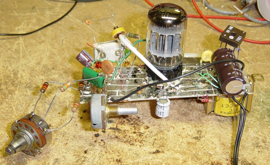 |
On the left, is the Regeneration control. It works by varying the B+ to the plate of the RF stage. The optimum setting is a little below oscillation, where the audio level comes up and selectivity increases. If you increase it beyond this point, the audio will start to become "muddy" as the Q is multiplied, and bandwidth reduced. Continuing to increase this will cause oscillation. This can be useful for SSB or CW reception, but not for listening to AM stations. ;)
The next pot over is the volume. The yellow transformer at the right is the B+ step-up. It takes the 15VAC from the "wall-wart" and steps it up to about 140v. This is plenty to get very good performance from this rather simple radio!
There is a point to be careful, with pins 2 & 3! Pin 2 is the pentode plate, and 3 is the center triode's grid. In this circuit, that would make an ideal feedback path between the output and the 1'st audio stage input, so layout is critical, here.
The unusual-looking breadboard is homebrew. I took a piece of plain PC board, and etched the pattern with a small, pointy file. Then I tinned it with solder, added the socket and then the components. The cathode resistor of the pentode was done by "lifting" the tube socket's pin from the board, and putting the R between the pin & the board. This simplified the rest of the layout, as I could use the larger foil area as a convenient ground.
| Back view of radio |
|---|
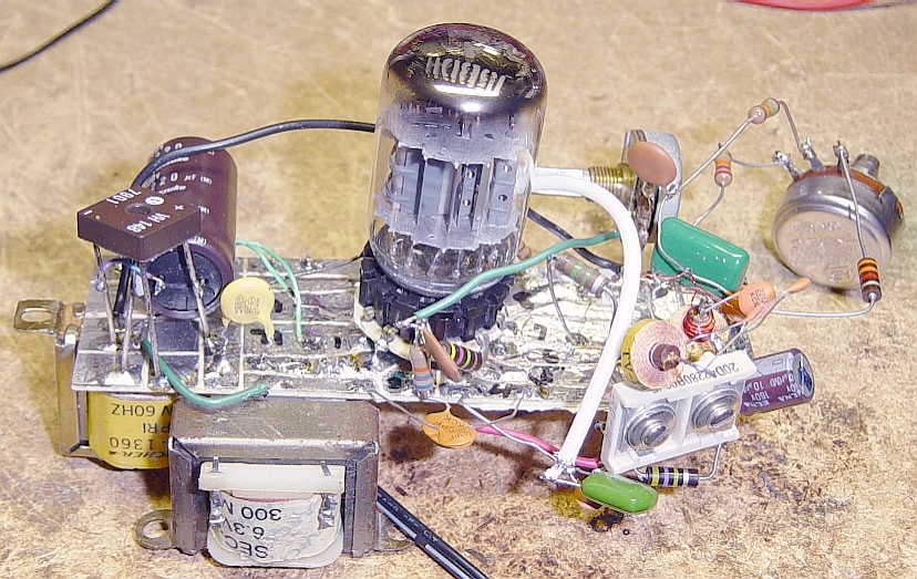 |
Here's the backside view. The 6.3v transformer is the audio output to the speaker. The dual trimcap is the radio's tuning and band-reject filter. Because I live only about a mile away from two AM stations on 1300 and 1340, their signals are quite strong. This first trimcap & coil form a series-resonant ckt, to shunt those stations signals to ground, while allowing other signals thru. The other trimcap is the tuning control for the radio. This radio is intended to be a monitor, where you set it to the desired station and just leave it set there. It works quite nicely in that capacity! (It needs an external wire antenna. I use a nearby metal shelf, which works perfectly.)
| Bottom view of radio |
|---|
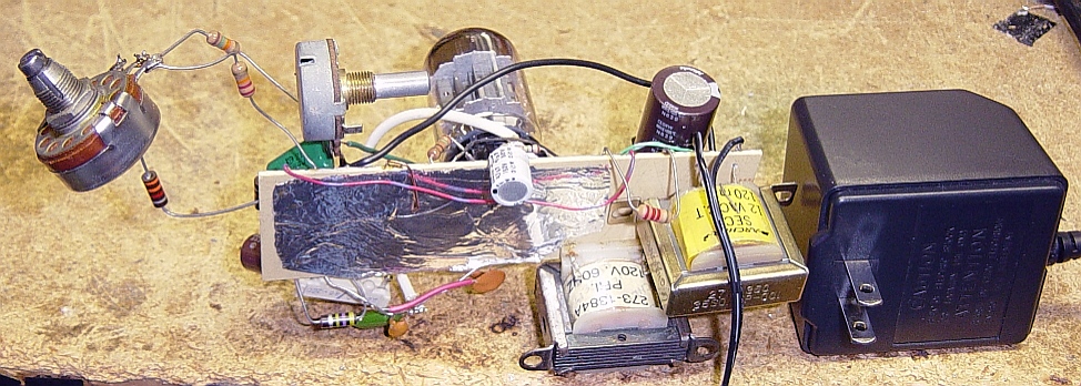 |
For this bottom view, I decided to include the "wall-wart" in the picture. It's a 15VAC, 1-amp unit, which is just about right for this application. The foil shield on the bottom is simply a piece of aluminum tape. A small piece of wire from the component side is bent around to make contact with this shield. That helped to stabilize the radio.
| Schematic of 1-tube radio. |
|---|
 |
Although this is a pretty basic design, it's customized to work with this particular tube & it's unusual "breadboard" layout. The power supply is not included in the schematic, since ANY source of 15V & 140v can be used.
If I can get my hands on another one of these tubes (or similar) I may make a small AM transmitter out of it! :)
*** DISCLAIMERS ***
(Keep the lawyers happy.)
*ALL* Information presented here is done so without warranty or guarantee of any kind. Author assumes no responsibility for the use or inability to use this information. Author also assumes no responsibility for the ability or inability to complete the projects, above. This project uses potentially harmful voltage! (140VDC) If you are not sure of what you're doing, ask an experienced friend to help. ALWAYS "pull the plug" and ground the caps to make sure there is no high voltage when working with this unit.
This information is presented as educational information only. No guarantee is made as to its fitness for any purpose. All risk is assumed by the person who choses to use this information.