God Bless America!
N1NKM's Mini audio osc |
|---|
 |

400 Hz oscillator
| 400 Hz oscillator V 1.0 |
|---|
 |

N1NKM's Mini audio osc |
|---|
 |

| 400 Hz oscillator V 1.0 |
|---|
 |
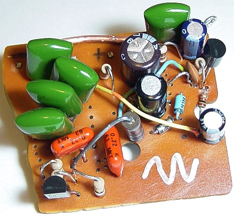
This project was the first one I built using my brand-new Dremel tool... I used an engraving bit to etch the copper, and a very tiny drill bit to make the holes for the component leads... but I went a little overboard with some of the holes! ;)
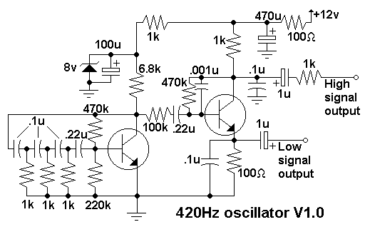
Aside from Dremel tool practice, I needed to run some tests on some audio amps. I needed a nice, clean sinewave oscillator. Since I don't own a commercial unit, and didn't really want to use the computer soundcard, I decided to build this little guy! It's a 2-transistor ckt, with one as the osc, the other a buffer/driver. This allowed me to have two signal levels/impedances: One at the Q2 collector with 1K ohm Z at a higher signal level, the other from the Q2 emitter at 100 ohm Z, with a much lower level. (It works great for testing hearphones!)
| Bottom of 400 Hz osc |
|---|
 |
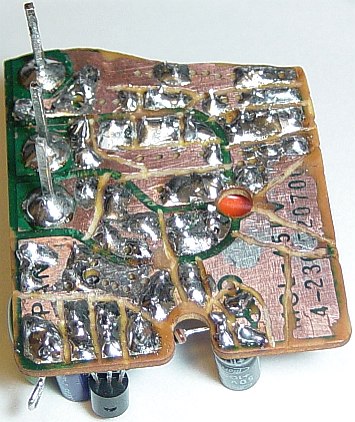
Here is the bottom view. This was a scrap PC board that I rescued from some old 1970's vintage stereo system. It was for a lamp, and it had a rather LARGE blank copper area... which is why I used it! :) Dremel tool in hand, I etched that puppy and built my oscillator on it. (This was before I splurged and BOUGHT some copper clad boards, but I digress.) That is why you see some odd-looking text on the corner of the board.
This project also served as a good place to get used to the new Dremel tool. The engraving bit worked OK, but I later discovered that it's much faster and easier to use the cutting wheel. (Just make the traces & lands all straight lines.) Save the curvy stuff for only where it's absolutely needed! ;) Besides, the cutting wheel lasts a whole lot longer than the engraving bit, which starts to get dull after only a few small PC boards about this size have been etched with it.
| 400Hz osc schematic |
|---|
 |
Here's the schematic. As you can see by Q1, it's the classc phase-shift circuit, using 3 caps and 3 resistors, but with the typical N1NKM twist. ;) Rather than try to figure out the values of the bias resistors to make that last r/c network, I just add an extra cap of larger value, and use standard high value bias resistors. More parts, yes, but it's my lazy way of avoiding punching a hundred buttons on the calculator! ;)
Those of you with a sharp eye may have noticed that there are TWO diodes in the top photo, but only ONE is shown in the schematic. That's because I only have 5v and 3v zeners, and needed an 8v... so there ya go. ;) By giving it this simple regulator, the frequency and purity of the sinewave stays pretty constant as long as the supply voltage stays between 8 to 20v.