God Bless America!
UPGRADE your RigBlaster™ Plus!!!
N1NKM's

RigBlaster MODS page! |
MOD
it! |
NOTE to Dialup users: this page has several 30K and 40K pictures, which may take a few moments to load. Please be patient.
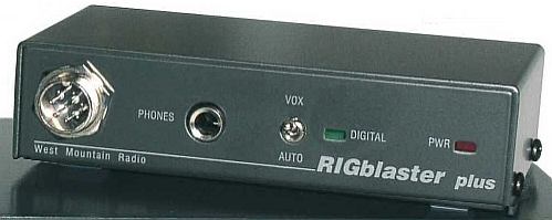
All by itself, it's a really great unit, and I cannot recommend it highly enough! I got mine in 2003, and have been using it ever since! Shortly after getting it, I modified it. (Hey, this is WILLIE, here... I modify EVERYTHING, OK? Hihi!) ;)
I changed the CW jack (since I never do CW, anyway) to serve as a Receive Audio Output jack, instead. The main reason for this, is because my rig is downstairs and my computer is upstairs! Since I had already run the cables from the shack to the computer room, I didn't want to run ANOTHER wire just to bring audio, when it was already there inside the RigBlaster™, right on the MIC cable!
(WARNING: Modifying the RigBlaster™ VOIDS the warrany! Do so at your own risk!)
Here is how I originally modified my RigBlaster™ Plus
to bring receive audio out through the "CW" jack:
| PC board view, TOP |
The red circle indicates where to CUT a trace. |
REMEMBER: If you do ANY of this, you will VOID YOUR WARRANTY! Proceed at your own risk!
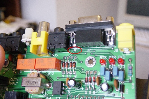
| PC board view, BOTTOM |

This shows where to add a 4.7K resistor, jumper wire, and the red circle shows where to cut a trace and ground the SLEEVE pin of the jack. One end of the resistor is connected to the jumper which bears your rig's audio output. (I have an ICOM, which uses pin 8 for rx audio.) The other end goes to the jack, with the TIP and RING jumpered together. (A stereo plug thus gets mono. If you use a mono plug, do NOT jumper tip to ring, use only tip.) |
This is the original mod that I made to my unit shortly after I received it. (I wasn't worried about voiding the warrany, since I knew that if I fried it, I could easily fix it myself.) Keep scrolling for the latest and greatest mods! :)
At the end of Jan 2007, I made some more VERY MAJOR mods to this unit. NOTE: THIS IS NOT A PROJECT FOR BEGINNERS!!!!!! Unless you are VERY skilled with soldering and metalworking, you run a great risk of RUINING your RigBlaster™ if you attempt these mods! Proceed at your own risk.
If you want a GREAT RigBlaster™ box that you WON'T need to modify like this, check out the "Pro"! It's worth the money. Trust me! I just got one, (Jan 2008) and have played with it a little. (More info near bottom of page.)
Here's what I did to make my "PLUS" into a "PLUS+" (Or a "Mini-Pro".)
| Front view of RB Plus+ |

Click pic for LARGE view. |
As you can see above, I installed a pot and a power switch on the front panel. I removed the little trimpot from the back of the RigBlaster™ pc board and brought the wires out to the new pot on the front. I also did some more rewiring inside, and added a "mute" relay, to cut the audio to the speakers during transmit. Then, I added a resistor network across the relay to pass a small amount of audio, since the DEAD SILENCE was rather disconcerting! ;) The relay passes stereo audio directly to the speakers when the unit is receiving or is powered off. During transmit, it bridges to mono.
I am happy to report that it all works VERY nicely! :) If you decide to do any of this, just be VERY CAREFUL when removing anything from the RB pc board! The copper traces are VERY DELICATE and will "lift" (thus ruining them) fairly easily! Use ONLY a SMALL wattage soldering iron and CAREFUL solder-removal techniques! This is why this is NOT a project for beginners!
This is ESPECIALLY true of the little trimpot in back, and the Audio Out jack to cut the traces underneath it. You want to still have the eyelets in the PC board to hold this jack in place after you solder it back in.
| PC board, top view of RB Plus+ |

Click pic for LARGE view. |
By clicking the picture, you will get the LARGE view, which is very big. This is so that you can see the details, especially around the relay! It is a DPDT unit. You can use virtually any miniature 12v relay as long as it fits! :) Sealed units are preferred, since you're dealing with low-level audio signals.
| Front view of RB Plus+, cover off |

Click pic for LARGE view. |
Here is a view of the front of the unit with the cover removed.
| Bottom of PC board |

Click pic for LARGE view. |
Here is the bottom of the PC board. I chose to drill a small hole thru the board to run the wires to the audio jack from the relay. It really isn't necessary to do this, since there is PLENTY of room to run the wires around the cutout near the mic connector... this is actually better than drilling a hole! When drilling, it is VERY easy to "miss" and drill right through a trace! I actually did this, and kicked myself! So, I had a little repair to do before I was able to continue the mod... a word to the wise. :)
Since disconnecting the CW jack, that left one of the opto-isolators on this board UNUSED. That seemed like a waste. I didn't know if the one opto could handle powering BOTH relays (the existing relay in the RB unit and the added one) and I didn't want to risk frying it to find out! Therefore, I wired the other opto to power the added relay. Putting another jumper onto the terminals near the RS232 port (as is visible in the large TOP VIEW pic) routed the computer control to BOTH optos, thus both relays. This makes the mute circuit independent, and doesn't add any significant stress to the existing circuits. It was a win-win! :)
One of the trickiest parts of these mods involves removing the Audio Out jack from the PC board. Make sure you have a GOOD "solder sucker" device! (Mine is a spring-loaded "POP!" type, which works OK.) You have to CAREFULLY remove the jack, then cut the traces going to the opposite sides of the jack... NOT the trace that goes to the part near the hole! That is the common, and you want to keep that trace. The traces are located under the jack, which is why this part is so delicate.
The relay breaks the circuit between the two jacks during transmit, passing the audio through the resistors, to drop the level to 10%. (A 1K with a 10K in series.) During receive, the relay simply connects the two jacks directly, which was how they were in the original RigBlaster, allowing normal stereo audio from your computer to your speakers.
| Relay wiring diagram |

The colors I use here are different than in the actual project simply to make it easier to explain the diagram. Starting with the 1K resistor at the upper left, that dark yellow lead connects to the COMMON (sleeve) of the Audio Out jack. The blue and purple wires go to the left. The blue to the output jack, the purple to the input. The green & brown wires are the right channel. The green goes to the output jack, the brown to the input. The leftmost two contacts are connected together. These are the Normally Open. the far right connections are the coil with a diode to protect the opto-isolator. The red goes to the power supply, and the black to the opto chip's output. (Pin 5) Pin 4 of the opto (U2) needs to be grounded. |
In the photo of the bottom of the board, those small yellow wires coming from the jumper area are to BYPASS the PTT when the POWER switch is turned off. (This allows the mic to still key the radio when the unit is off.) There is a small issue here- when the rig is powered on and the RigBlaster™ is off, the PTT voltage from the rig is getting back into the RB, and causing the POWER LED to glow dimly. With my radio, this hasn't been a problem. It actually serves as a nice reminder that the rig is ON when I'm upstairs! :) YOUR radio may not like this, so you may want to omit the power switch if this becomes a problem.
I also chose to use TWO resistors for the receive audio mod, one feeding each channel, rather than one resistor feeding both.
WHY did I do all of this?? Well, unfortunately, I have had some problems getting the "Pro" to work on my setup because of my very unsual station configuration. I have already confirmed that there is NOTHING WRONG with the "Pro"... it simply was never intended to be used in a configuration where the rig is about 40 feet away from the computer, and down in the basement! I'm just getting too much RF and ground-loop problems with these excessively long wires. I will most likely end up using the Pro on my basement computer, instead. In any case, it is definitely a KEEPER! :) The theory is that the long wires and the impedances inside the Pro are not a good mix. The impedances of the Plus are obviously different, as it works fine... and even after modification, it still works 100%!
This gives me two of the features I liked MOST in the Pro- transmit audio muting, and a pot on the front to vary the transmit audio! With the pot at MAX, I set the soundcard audio so that the ALC in the radio JUST BARELY activates. Then, I can use the RB's front panel pot to set my power level instantly and on-the-fly. :) I've already had several PSK QSO's with this modified RigBlaster™ Plus+ and I'm VERY pleased with it! :) Now, I just need to figure out if I want to keep calling it the "Plus+" or the "Mini-Pro"... Hmmmm.... :/
Please E-mail me with any comments/suggestions.
Return to HOME page
*** DISCLAIMERS ***
(Keep the lawyers happy.)
*ALL* Information presented here is done so without warranty or guarantee of any kind. Author assumes no responsibility for the use or inability to use this information. Author also assumes no responsibility for the ability or inability to complete the projects, above. MODIFICATION OF THE RIGBLASTER™ WILL VOID IT'S WARRANTY! If you are not sure of what you're doing, ask an experienced friend to help! Far better to WAIT and have it done RIGHT, than to make a mistake and ruin your expensive RigBlaster™!!
This information is presented as educational information only. No guarantee is made as to its fitness for any purpose. All risk is assumed by the person who choses to use this information. While the author's experience indicates that this proceedure was effective, any attempt to build/modify these devices IS AT YOUR OWN RISK. Extreme care must always be excercised, this is at the builder's SOLE RISK.