
God Bless America!
N1NKM's HAM page 5 |
|---|
MODS! |
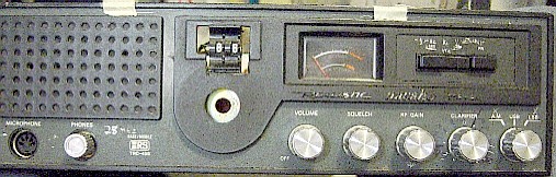
This page displays my very first HF radio, and how YOU can modify one, yourself!
 |
| N1NKM's HAM page 5 |
|---|
MODS! |
This page displays my very first HF radio, and how YOU can modify one, yourself!
|
The mod is VERY simple! Replace the crystal "X3" which is the right-most one of three, right inside the little "wall" around the PLL circuitry. You will need an 11.933 Mhz crystal. (That will give you UPPER SIDEBAND. If you want to add LSB & AM, you'll need to calculate those x-tal freq's.) The rig will cover almost all of the 28.000 to 29.999 band, so care must be excercized to remain within band! (28.000 - 29.700)
You will also need to RE-TUNE the PLL circuit, so that it "locks" on the new band. This can pretty much be done by ear... you'll hear a "buzzing" sound in the speaker when it goes out of lock. That buzz will change pitch as you tweak. Tweak it until it stops, then go a little further, until it starts again. The point you want is in the MIDDLE of the range where it doesn't buzz. You'll need to check the stability at both ends of the band you wish to cover. I don't think it will go the whole 2Mhz, only a portion of it... but it's a pretty large portion! The "cans" you need to tweak are the two single ones between the 3 X-tal sockets and the PLL chip. The one on the right (if memory serves) is the main one.
| TRC458 PLL section |
|---|
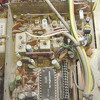 |
You can see in this image, that I only have ONE x-tal installed. This is because I did not actually ORDER the correct one... I used one that I scrounged from some other CB radio! (They make great "organ donors"!!) Heh heh! :) The one I use is 11.596Mhz. That results in my BCD thumbwheel switches being off by 10Khz. I live with it, for now... but at some point, I may actually order the right frequency x-tal, and have them read correctly! :)
The receiver's front end will need to be retuned. That's pretty simple, and can be done by ear, also. (Having a weak signal on the air, or a stable signal source to test with, is helpful, tho!) There are 2 small RF "cans" right by the modulation transformer, at the left-rear of the board. There is also a "double-barrelled" one to their right. Those 4 adjustments are the ones you want. Don't worry about the "ADMIT NO ADJ" can... that is for the NOISE BLANKER, so you don't need to mess with it.
I replaced the "channel" switch with a pair of BCD thumbwheels, which select 0 to 9. I also had to modify the clarifier, to widen it's range.
There is a diode in the clarifier circuit that needs to be removed, to allow the clarifier to affect both the TX and RX. You also will need to change a few resistors, to give it a wider range. (There is one between pot & ground, and one between pot and + voltage. I used 100 ohms for both.)
You *MUST* use a voltage regulator to power the modified clarifier circuit. If you don't, the frequency will move as you transmit. It wants to see about 9 volts on the "top" of the pot. (An LM7809T will be perfect.) That should give you about +6 to -5 Khz range. You can't get more than -5, since that is what you get at 0 volts. You don't want it to see more than 9v, to avoid damaging the varactor diode.
There should be information online regarding this mod. If you can't find it for the TRC458, try looking for the PRESIDENT line, like GRANT or WASHINGTON. In the 1980's, those radios used the SAME circuit board & PLL chip. (There were only minor component differences between radios.)
You will also need to cut two copper traces in the transmitter driver stages, around the "double-barrelled" RF can, L37. It is right near the front & center of the board.The board has a trace going to the CENTER pins on each end of that double RF "can". You want to cut those traces (Carefully, of course) and jumper to the END pins, instead... leaving the center ones disconnected. In my radio, for some reason, I used a .05 capacitor to jumper the side closest to the little torroid, L36. I made these mods over 20 years ago, so it's kinda hard to remember why I used that cap. You will also need to re-peak the transmitter stages, too.
| This is a rough diagram of the L37 mods as seen from the BOTTOM of the board: |
|---|
 |
The RED circles show where to ADD the jumper (upper right) and the .05 uf cap (lower left). The BLUE circles are where you need to CUT the existing traces. The light green is the COPPER and the DARK GREEN is plain circuit board. The WHITE (silver) areas are the solder pads. These mods are necessary to broadband the TX stage enough to cover more than 400Khz. Remember... this thing *WAS* a CB!!! We're transforming it into a HAM radio! :)