
God Bless America!
N1NKM's Mini audio amp |
|---|
 |

MINI headphone amp
This litte beauty has PLENTY of power for headphones!
| Mini headphone amplifier V1.0 |
|---|
 |
| N1NKM's Mini audio amp |
|---|
|
This litte beauty has PLENTY of power for headphones!
| Mini headphone amplifier V1.0 |
|---|
|
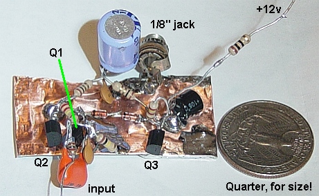
As you can see by the quarter, this whole thing is only about 1" by 2". It puts out approximately 100 milliwatts with a 12v supply. Believe me, that is MORE than enough for headphone listening! With a decent 3" or 4" speaker in a good enclosure, it's plenty for tabletop use, too. I built this so that I could test my homebrew RIBBON MICROPHONES while listning to headphones... but it was so nifty, I decided to put it online, in case anyone wanted to build one like it. You can use it to amplify any "line level" audio source to more than enough power to drive a headset. Wiring up a pot as a volume control is pretty straightforward, no need to go into that, here. :)
An idea just occurred to me... you could use a piece of double-stick tape, and literally mount this to the side of a 9v battery, and use it as a very portable, simple signal tracer. That's PRACTICAL BTN! :)
| Headphone amp V1.0 schematic |
|---|
 |
| Mini audio amplifier V2.0 |
|---|
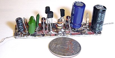 |
Here's the backside view of V2.0, a more permanent version of the V1.0 unit. A few parts have different values, but otherwise the circuit is the same. The input transistor is now a 2N5089, which has a lot more gain, so it needs different bias resistors.
| V2.0 front view |
|---|
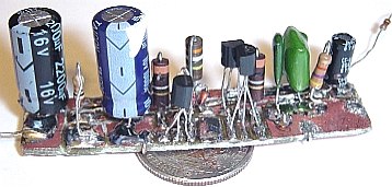 |
In this view, the speaker output lead is on the left. Next to it (between the two large caps) is the +Vcc solder land. On the right, front is the ground land. (Near the green caps.) Coming off the back and right is the input.
It's built on double-sided copper clad board. The bottom is mostly an unbroken ground plane. Connections can be seen bridging foils on top to the bottom. I originally etched this to use some TO-220 output transistors, which have their pinout as ECB. That's why the output transistors are turned sideways, here. They are EBC.
Strangely enough, I actually get better output from these little TO92's than I did the others! Obviously some impedance/driver issues. I was using a "large TO92" style transistor & a 300 ohm resistor in place of the 2.2K. The feedback R was 47K. It worked, but not as well as the 3904/06 pair with 5089 driver, so here we are!
| Audio amp schematic V2.0 |
|---|
 |
The only changes from V1.0 are to some component values, as shown above. It's got a bit more gain and a bit more output than V1.0. Capable of ~200mw, this one is good for powering a speaker in a 12v device. Idle current is 7ma. At full volume (before severe distortion) the current draw is ~30ma. Yeah, I know, it's probably a lot easier to just use an LM386-based amp... Perhaps I'll whip one up later. This one was just fun to make! :) With beefier input & output caps, this one's bass response is quite good. To think about it... what sense does that make, when it only delivers ~ 200mw? Hey, it's only spare parts, here... no big deal. ;)