
God Bless America!
N1NKM's MODULATOR!
N1NKM's

HAM page 7 |
HOMEBREW!
Modulator |
NOTE to modem users: this page has several 50K+ pictures, which may take a few moments to load. Please be patient.
This page contains photos of my homebrew audio amp/modulator.
I like to think of this as Marvin the Martian's "Illudium PU-36 explosive space modulator!" ;)

Click Marvin to hear him say it! ;) (small MP3 file)
| Front view |
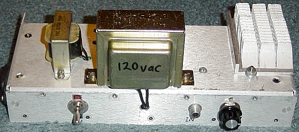 |
It's pretty simple. Power supply choke, transformer, and additional heatsink are on top. On front are the power switch, the input, and the volume control. Barely visible on the left is a standard 3-prong AC power jack, used on virtually everything with removable power cords. Just out of sight on the right, is the 1/4" output jack. It will deliver about 25 watts into anywhere from .5 to 4 ohms. Into 8 ohms, it gives me about 12 watts. When driving an experimental AM transmitter via a 3VAC transformer in reverse, this unit gets quite warm while delivering 100% clean AM. That transmitter is still in development, though, so no pics, yet. It's currently using a pair of 12HL7's in parallel with a 400v B+ supply. That's pushing the tubes a bit, but the plates aren't glowing, so I'm still OK. I may rewire it to work with a pair of 6BQ5's instead... not sure if this unit will have enough "oomph", though, but if it does, then it will become part of the new "BOB Jr". ;)
| Inside of modulator |
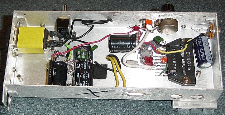 |
Here's the inside view. Top left, the AC power connector. It's nice because it incorporates excellent RFI suppression! (It was salvaged from a defunct computer monitor.) Next to that is the power switch. Below that, the power supply rectifier & caps. The small green caps are .01's across all pins of the rectifier for RF bypassing. You'd be surprised just how effective this is at eliminating that annoying "buzz" from transmitters! There is another cap electrically close to the chip to provide better transient response. The chip is a surplus STK015. Above it, the audio input with a small LC filter to reject RF, and the volume pot. There is also another small coil right at the input pin to the chip. There's no RF getting into THIS puppy! Hihi! :)
It's also probably my "neatest" project, construction-wise. That's pretty much due to the low parts-count, and straightforward layout. Having plenty of room inside the box helped, too.
BTW, this nice aluminum box came from a cell site. It was one of a number of "dead" modules that were being replaced. I'd sure like to get my hands on more of these! They're pretty rugged, about 1/8" thick. You sure can't beat 'em for RF-proofness, either! Because it's aluminum, it's pretty easy to work with, too!
You are welcome to E-mail me with comments/suggestions.
Constructive messages are welcome.
Abusive messages will be deleted. It's that simple. :)
Here's my HOME page
*** DISCLAIMERS ***
(Keep the lawyers happy.)
*ALL* Information presented here is done so without warranty or guarantee of any kind. Author assumes no responsibility for the use or inability to use this information. Author also assumes no responsibility for the ability or inability to complete the projects, above. To avoid damaging the chip, ALWAYS "pull the plug" and ground the caps to make sure there is no voltage when working with this unit.
This information is presented as educational information only. No guarantee is made as to its fitness for any purpose. All risk is assumed by the person who choses to use this information.